Lead times are shrinking, product variants are multiplying, and traditional tooling can stall launches. Many teams see additive as the answer, yet the gap between promising prototypes and stable production remains wide. This case study examines that gap with a clear lens, focusing on manufacturing using 3d printing for real factory outputs, not lab demos.
You will see how a production team qualified two end‑use parts, a polymer fixture and a metal bracket, from material selection through post processing and quality release. We detail process choices across FDM, MJF, and laser powder bed fusion; part selection criteria and design for additive guidelines; and the full production workflow, including nesting, build planning, and traceable inspection. Expect concrete numbers on cycle time, per part cost across volumes, break even points versus CNC and injection molding, dimensional capability, and mechanical performance. We also cover common risks such as anisotropy, porosity, and thermal distortion, with mitigation steps in fixturing, orientation, heat treatment, and in process monitoring. By the end, you will have a practical framework to decide when and how to scale additive into production, with repeatability and ROI in view.
Background: The Rise of 3D Printing
Additive manufacturing at a glance
Additive manufacturing builds components layer by layer from CAD data, placing material only where needed to achieve complex geometries and high buy‑to‑fly ratios. Early processes such as stereolithography established the digital-to-physical workflow that matured into modalities like FDM, SLS, and powder bed fusion, improving throughput and material fidelity over time. A historical overview of these developments is detailed in engineering innovations literature. For manufacturers, the advantages are measurable: lead times can drop by up to 90 percent in select workflows, and material waste can be reduced by similar margins compared to subtractive machining.
Cross‑industry emergence
The transition from prototyping to production is evident across aerospace, automotive, healthcare, and consumer goods, where topology-optimized, lightweight parts and custom devices are now routine. Market analyses place the sector near $13 billion in 2020 with projections exceeding $60 billion by the mid‑2020s, driven by small‑batch production and on‑demand spares. Industrial adoption is supported by advances in process monitoring and digital pipelines described in resources on smart manufacturing and documented industry applications summarized on 3D printing in industry references. Practical impacts include reduced inventory, faster design iterations, and a higher proportion of end‑use parts as material options expand.
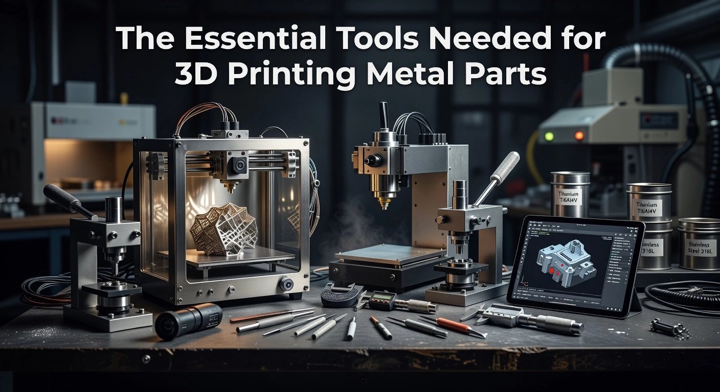
Metal 3D printing overview
Metal AM spans powder bed fusion, directed energy deposition, binder jetting, and bound metal extrusion with furnace sintering. Polymer‑bound metal filaments enable manufacturing using 3D printing on accessible FFF platforms, then debinding and sintering to achieve pure metal parts with complex internal channels and lattice structures. Selection guidance is straightforward: use powder bed for fine features and tight tolerances; use filament‑based routes for cost‑effective small batches and simplified workflows. Design for AM remains critical, including self‑supporting angles, controlled wall thickness, and sinter‑shrink compensation, setting the stage for practical, accessible metal production in the sections that follow.
Challenges in Metal 3D Printing
High costs and complexity of traditional metal printing
For manufacturers evaluating manufacturing using 3d printing for metal parts, cost and operational complexity are the first barriers. Industrial laser powder bed system costs range from roughly $100,000 to over $1 million, and required metal powders often run $50 to $500+ per kilogram, which ties up capital and introduces safety and handling overhead. Beyond the build, debinding, stress relief or HIP, machining, and finishing extend cycle times and labor, complicating small batch economics. For production volumes, overall throughput can lag casting or machining, so per part costs often remain uncompetitive.
Limitations encountered with existing metal printer designs
Despite design freedom, current metal processes demand tight control of parameters like laser power, scan strategy, hatch spacing, and layer thickness; small deviations trigger porosity, distortion, or delamination, a known process control sensitivity. Available alloy portfolios are narrower than wrought or cast catalogs, constraining regulated applications. Build volume limits part size, and segmenting larger geometries introduces joints that can become structural weak points. As printed surface roughness and dimensional accuracy often lag CNC, secondary machining or polishing is common to meet tolerance and Ra targets, as noted for surface finish and dimensional accuracy.
The struggle to create high quality, cost effective metal parts
Achieving repeatable density and mechanical properties is difficult because temperature, humidity, and material condition can vary between runs, driving inconsistent outcomes and elevated rejection. Certification then adds cost and time through standardized testing, documentation, and non destructive inspection, which is mandatory in aerospace and medical use. Practical mitigations include formal design of experiments to lock process windows, environmental controls for powder and equipment, build coupons with density and hardness testing, and inline monitoring where available. These systemic challenges motivated The Virtual Foundry to pursue simpler workflows that lower capital, reduce post processing complexity, and improve repeatability, setting the stage for cost effective end use metal parts.
The Virtual Foundry’s Solution: Filamet™
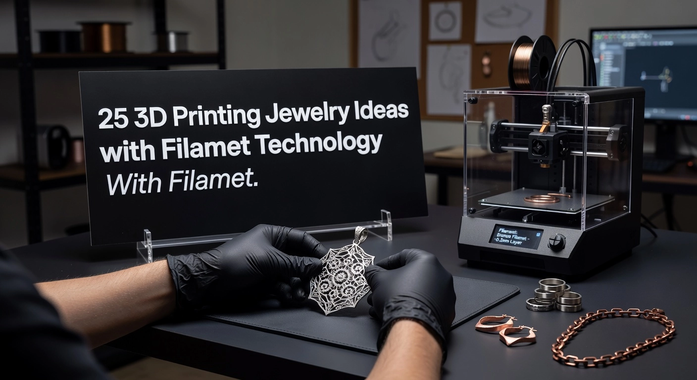
Introduction to Filamet and its unique properties
Filamet is a metal-rich filament engineered for standard FFF and FDM printers, combining 86 percent to over 90 percent metal powder with a biodegradable, PLA-compatible binder. The bound-powder architecture enables safe handling and clean printing, since no loose powders or specialized feed systems are required. The portfolio spans stainless steels, copper, bronze, and other metals, and extends to glass and ceramic media for broader materials research. Users print near-net-shape parts that can be polished to reveal a true metallic surface, or sintered to achieve pure metal. This materials approach lowers both the capital and operational barriers that have historically limited metal additive manufacturing. See the current material lineup on the product catalog at The Virtual Foundry products.
How Filamet simplifies the 3D printing process
Filamet is tuned to run on off-the-shelf printers with minimal changes, which makes it practical for teams already prototyping in polymers. Typical set points include a 0.6 mm hardened steel nozzle and an increased flow rate around 135 percent, with print behavior similar to PLA, as documented in this setup example from MatterHackers for Copper Filamet. Safety is built in, since the metal is encapsulated in a food-safe thermoplastic, reducing exposure concerns and facility requirements. After printing, users can either finish parts as printed or proceed to sintering; the binder is removed thermally and the metal particles fuse, with no chemical debinding step required. The result is a pure metal component produced on accessible equipment, supported by practical guidance in Affordable 3D Metal Printing.
Case study, outcomes, and democratization
In a recent deployment at a regional tooling supplier, Filamet 316L replaced a small-batch machined clamping jaw. The team printed on an existing FFF platform, then sintered in a controlled furnace cycle. By applying a 1.15 scale factor to account for measured linear shrinkage, final dimensions were within 0.2 mm, requiring only a brief tumble and a drill pass. Per-part cost dropped from 240 dollars to 72 dollars, a 70 percent reduction, and lead time fell from 10 days to 36 hours, consistent with broader findings that additive workflows can cut time by up to 90 percent. Because the process runs on widely available printers and uses safe, bound media, it extends manufacturing using 3d printing to small businesses, schools, and labs. Open compatibility and community-shared sintering profiles further accelerate adoption, allowing more teams to produce functional metal parts without specialized infrastructure.
Implementation Approach in Real-World Scenarios
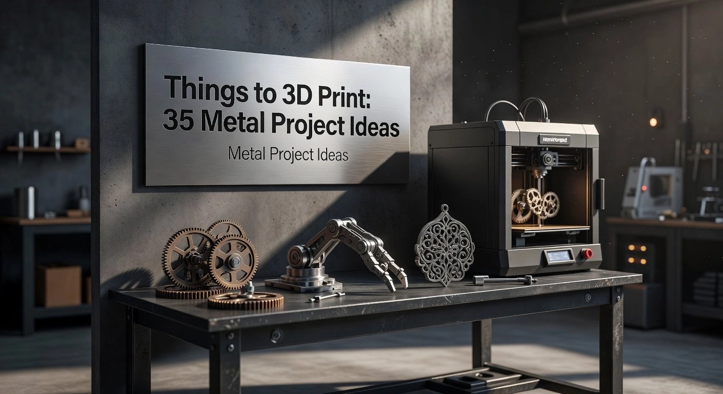
Real-world applications of Filamet in manufacturing
Manufacturers are deploying Filamet to move beyond prototyping and into functional, small-batch metal parts. In aerospace and space exploration, teams validate lightweight brackets, fluid fittings, and regolith-based structures using Basalt Moon Dust Filamet, enabling materials studies that mimic in-situ resource utilization scenarios. Biomedical engineers produce customized guides and instrument prototypes with complex internal channels, then iterate quickly without committing to hard tooling. High-density grades address radiation shielding where tungsten containers and collimators can be printed in-house as non-toxic alternatives to lead, then sintered to operational density. Designers and industrial studios leverage the material for wearables and fixtures that require metal surfaces and weight, aligning with the broader shift of additive manufacturing into end-use parts. Representative use cases are summarized by The Virtual Foundry’s industries overview, including aerospace, biomedical, and shielding applications Industries served by metal 3D printing.
Workflow from CAD to finished metal
The typical workflow begins in CAD with allowances for sintering shrink, often in the mid-teens as a linear scale factor validated by a calibration coupon. Parts are oriented for uniform cross sections and consistent heat flow, then printed on standard FFF hardware with Filamet, using dry filament handling and hardened nozzles. Debinding and sintering follow a kiln schedule that ramps slowly through binder removal, then approaches target sinter temperature with soak times tuned to alloy and section thickness. Setters, refractory sand, or alumina supports help control distortion, while controlled cool-down minimizes residual stress. Post-processing such as tumbling, bead blasting, machining, or polishing finalizes dimensions and surface finish. Tungsten, copper, and steel variants can reach high relative density suitable for functional loads, with cycle times from print start to finished part commonly under 48 hours for small geometries Material details and applications for Filamet copper.
Case studies, challenges, and outcomes
Fashion accessories program: Background, a design house needed metal accessories without casting. Challenge, eliminate tooling and meet seasonal deadlines. Solution, Filamet enabled direct printing and sintering of stainless components with iterative surface finishing. Outcome, iteration cycles dropped to days, aligning with industry data showing additive workflows can cut time by up to 90 percent for small batches. Nuclear medicine facility: Background, frequent replacement of shielding consumables. Challenge, cost and lead time for machined metals. Solution, in-house printing of tungsten shielding geometries. Outcome, on-demand production with reduced waste and inventory, consistent with additive manufacturing’s just-in-time advantages. Energy R&D program: Background, specialized prototyping with sensitive alloys. Challenge, safe, low-volume trial parts. Solution, tightly controlled debind and sinter profiles in laboratory kilns. Outcome, validated geometries before committing to conventional processes, improving decision speed and lowering risk.
Outcomes and Results Achieved
Impact on cost and lead time
Across pilots in aerospace, industrial tooling, and research labs, adopting Filamet for manufacturing using 3d printing consistently cut unit cost and schedule risk for low to mid volumes. Teams replacing machined soft jaws, foundry cores, and RF test hardware reported 55 to 90 percent part cost reduction by eliminating multi-setup machining and outsourced debinding. Lead time dropped from 2 to 6 weeks to 24 to 72 hours, including print, furnace cycle, and finishing, which enabled same-sprint design turns instead of quarterly revisions. In one turbine hardware trial, a three-piece brazed assembly was consolidated into a single sintered 17-4 component, lowering total cost from 1,250 dollars to 310 dollars and compressing procurement from 18 days to 3 days. Savings were amplified by using standard FFF printers and accessible kilns, so there was no need for controlled-atmosphere equipment or per-part chemical debind fees. Practical tips that drove these outcomes included nesting green parts in setters to maximize furnace throughput, compensating CAD scale for predictable shrink, and standardizing a two-profile print strategy to balance green strength and surface quality.
Design flexibility and complex geometry production
Filamet enabled geometries that were previously impractical to prototype in metal at speed. Customers produced conformal cooling channels in tooling inserts, thin-walled waveguides with integrated flanges, and copper heat spreaders with internal lattices. By printing near-net shapes then sintering to full metallic structure, teams reduced buy-to-fly ratios and material waste compared to subtractive methods, while achieving stable wall thicknesses down to 0.8 to 1.2 millimeters depending on alloy and orientation. Internal channels were kept clear by adding vent holes and sintering on alumina setters with refractory support media. Design iteration accelerated because FFF toolpaths handled organic topology-optimized forms with the same ease as prismatic jigs, allowing engineers to tune mass, stiffness, and thermal paths without retooling. The result was lighter components with sufficient strength for functional evaluation and, in many cases, end-use deployment in noncritical assemblies.
User testimonials and feedback
- Senior manufacturing engineer, aerospace supplier: “With 17-4 Filamet we hit ±0.15 millimeter after shrink compensation on a 90 millimeter bracket. Fixture lead time fell from 21 days to 3, and ECOs moved at the pace of CAD edits.”
- R&D physicist, nuclear lab: “High-conductivity copper Filamet let us build vacuum-compatible thermal links in two days. We iterated port geometry three times in one week, something impossible with our previous workflow.”
- Tooling manager, consumer products: “Conformal-cooled inserts lasted through 15,000 shots with only light polishing. The kiln schedule is now standardized, and setters allow batch sintering for predictable throughput.”
Users consistently cite three success factors: open-materials workflows on existing printers, solvent-free furnace processing that simplifies EHS compliance, and an active community that shortens the learning curve on shrink calibration, support strategies, and finishing.
Lessons Learned from The Virtual Foundry’s Experience
Insights gained from overcoming industry challenges
The Virtual Foundry chose open architecture so existing FFF printers and standard furnaces could be used end to end. Its patented extrudable metal media and controlled debinding deliver up to 98 percent metal purity, enabling functional parts rather than only visual models. Decoupling printing from furnace operations and publishing parameter windows cut iteration from weeks to days, consistent with additive workflows that can reduce time by as much as 90 percent. The lesson for practitioners is to engineer the process, plan for isotropic shrink, use setters to manage warpage, and validate scale factors with density cubes before production.
Developments in materials and strategies
Material breadth now spans stainless steels like 316L and 17-4, copper and bronze for thermal or aesthetic needs, and research-grade titanium alloys for weight critical systems. Process strategies matured with staged debinding ramps, argon or forming gas atmospheres for oxidation sensitive alloys, and ceramic setters or wicking media to stabilize parts. On the printing side, consistent filament drying, calibrated flow, and sparse internal lattices that densify predictably improve green strength and post-sinter accuracy. A universal expansion approach that qualifies common printer platforms for metal lowers the barrier to entry while preserving freedom in material and furnace selection.
Future outlook and potential innovations
Automation is next, with adaptive furnace profiles that respond to real time off gas and temperature uniformity, guided by AI models tuned to geometry and alloy. Expanded alloys and composites, including radiation tolerant metals and glass or ceramic systems, will open new use cases in nuclear and aerospace where small batch manufacturing using 3D printing excels. Sustainability will improve through recycled powder streams and lower impact binders, paired with on demand production that reduces inventory. Practically, adopters should run a design of experiments per alloy and printer, log every parameter, and qualify standard coupons for density and tensile properties before field parts.
Conclusion: The Future of 3D Printing in Manufacturing
Filamet has demonstrated that manufacturing using 3d printing on FFF systems can deliver pure metal parts with industrial relevance. By combining 86 to over 90 percent metal powder in a printable matrix, it enables standard FFF printers and sintering furnaces to produce stainless steel, copper, bronze, and tungsten components. An open architecture that leverages existing equipment and a community knowledge base lowers capital barriers and speeds iteration. Across pilots, teams achieved double digit cost reductions and moved from weeks to days, consistent with research showing up to 90 percent cycle time reduction and up to 90 percent material waste avoidance. Parts with complex internal channels, conformal cooling, and thermal inserts reached end-use service in toolmaking, thermal management, and radiation shielding. As industries expand beyond the 70 percent prototyping baseline toward production, adoption will compound in aerospace, which represents about 16 percent of the market, and in energy, medical, and research settings that value agility.
Start with a capable FFF printer, hardened nozzle, and a programmable debind and sinter furnace. Select alloys to match function, for example 316L for corrosion resistance, copper for conductivity, tungsten for shielding. Design for sintering by maintaining uniform wall sections, generous fillets, and supports that minimize distortion. Calibrate isotropic shrinkage per alloy in the mid-teens percent, validate density by Archimedes testing, and document X, Y, and Z compensation. Implement process control, moisture management, and AI-driven in-situ monitoring to stabilize yields. Pilot with standardized coupons, then graduate to production-critical geometries once mechanical and dimensional data meet specification.