If you can print PLA, you are closer than you think to printing stainless steel. This tutorial demystifies metal 3d printing using Filamet™, a metal powder and polymer composite that you can run on a standard FFF printer, then debind and sinter to form near solid metal parts. We will translate metallurgy into practical settings and workflows, suitable for intermediate makers and engineers who already tune slicers and troubleshoot extrusion.
You will learn how Filamet™ differs from common filaments, including moisture handling, abrasion, and nozzle considerations. We will cover part design for sintering, wall strategies, infill choices, and green part strength. You will dial in slicing parameters like flow, temperature, speed, and retraction to minimize seams, binder pooling, and delamination. The guide explains debinding options, sintering cycles, kiln setup or service workflows, and how to predict and compensate for anisotropic shrink. We will walk through density targets, distortion control, supports and setters, surface finishing, and post processing. Expect practical calibration steps, troubleshooting for warping and cracking, and a checklist for safe handling and cost control. By the end, you will have a repeatable process from CAD to finished metal.
Understanding Metal 3D Printing
Overview of technologies
Metal 3D printing builds metal parts layer by layer from digital models, enabling complex geometries and controlled microstructures. Powder bed fusion techniques such as Selective Laser Melting use a laser to fully melt fine metal powders for high density parts; Directed Energy Deposition feeds wire or powder into a melt pool for repairs and large features. In binder jetting, a liquid binder defines a green part that is later sintered to consolidate metal; Ultrasonic Additive Manufacturing welds stacked foils at low temperatures, allowing embedded sensors. With The Virtual Foundry’s Filamet, standard FFF printers produce metal rich green parts that are sintered, and a conservative furnace ramp near 150°F per hour to roughly 900°F during debind helps prevent cracking.
Evolution and key milestones
The field grew from laser sintering research in the late 1980s and accelerated in the 1990s as lasers, optics, and powder metallurgy improved. The 2000s introduced electron beam processes and better in situ monitoring, expanding materials such as titanium and nickel superalloys. In the 2010s, lower costs and filament based routes broadened access beyond large factories, aligning with a shift toward digital qualification. Current research reports safer, stronger parts for aerospace and nuclear systems, and new AM tailored aluminum alloys retaining properties near 572°F are reshaping heat exposed designs.
Applications across industries
Aerospace uses lattice infill and conformal passages to reduce mass and consolidate parts while cutting waste relative to subtractive machining. Nuclear operators produce high quality spare parts on demand to extend plant life and mitigate obsolescence, supported by rigorous inspection and documentation. Artists and jewelers create filigree and micro lattices that can be tumbled and polished to a gallery grade finish, while manufacturers build tooling and fixtures rapidly. As a rule of thumb, metal AM is most economical for complex components or batches of roughly 1 to 20 units per year, and process selection should reflect part size, target density, and available post processing.
Getting Started with Filamet™
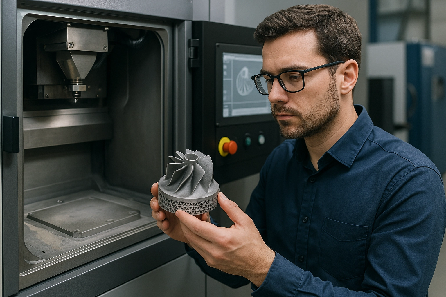
Introduction to Filamet™ as a printing material
Filamet™ is a metal filled filament for FFF printers, combining roughly 80 to 90 percent metal powder with a biodegradable, non toxic thermoplastic binder. It prints similar to PLA, then converts to near pure metal after debinding and sintering. Encapsulated powder improves handling safety compared with loose powders and keeps workflows accessible in typical maker or R&D environments. The approach excels for short run production, on the order of 1 to 20 units per year, where fast iteration and low capital cost matter. Use cases include manufacturing fixtures, art and jewelry, research coupons, and early aerospace or nuclear prototypes that require real metal properties.
Setting up your 3D printer for Filamet™ usage
Use an open architecture FFF printer, with a direct drive extruder preferred for consistent feeding of the dense filament. Install a hardened steel nozzle, 0.6 to 0.8 mm, to resist abrasion and reduce back pressure. Keep the filament path straight from spool to extruder, minimize bends, and consider a filament preheater to relax brittleness at the drive gears. Prepare a reliable build surface, for example powder coated spring steel, clean glass, or blue tape, and level carefully to protect the first layer. Maintain gentle enclosure airflow and stable room temperature to limit warp and improve interlayer bonding.
Basic printing techniques and best practices
Start with a 0.2 mm layer height, 2 to 4 perimeters, at least 6 solid top and bottom layers, and 70 to 100 percent infill to support sintering. Reduce print speed to roughly 50 percent of your normal PLA profile and raise flow to 110 to 125 percent to account for filament density. Use conservative overhangs and orient parts for even wall thickness to minimize distortion. After printing, debind by ramping about 150°F per hour to roughly 900°F, then follow metal specific sinter temperatures and atmospheres per alloy. Use setters or simple ceramic fixtures to maintain flatness, then finish by tumbling, sanding, or polishing to meet surface and tolerance requirements.
Exploring Design Flexibility
Designing for metal 3D printing: key considerations
Designing for metal 3D printing with Filamet requires attention to support, wall thickness, thermal behavior, and anisotropy. Overhangs above 45 degrees benefit from self-supporting angles or integrated lattices to limit support mass and post processing, see 5 key factors for metal AM design. Maintain wall thicknesses appropriate for the target metal and span length; thin features risk collapse during debind or sinter, while thick sections can collect stresses and warp, which aligns with guidance in what is metal 3D printing. Plan for debind and sinter by adding powder escape holes and generous radii at stress concentrators, and reserve 12 to 20 percent linear shrink compensation in CAD for FFF metal parts. Optimize orientation to align principal stresses with the strongest print direction and to manage heat flow, an approach that mitigates anisotropy as noted in design considerations for metal 3D printing.
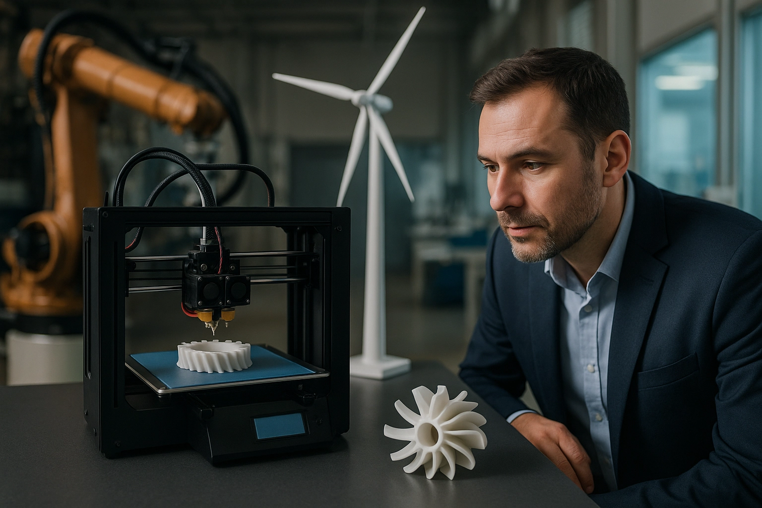
Leveraging complex geometries through Filamet™
Filamet enables closed internal channels, gyroid lattices, and conformal cooling paths that are not machinable, then sinters to pure metal for functional testing. Using standard FFF printers with metal-filled filament reduces fixture constraints and lowers prototype cost, while accelerating iteration for complex brackets, heat exchangers, and tooling inserts. For thermal tooling and heat exchangers, lattice infill increases surface area and reduces mass, which complements ongoing alloy advances where heat resistant aluminum systems are being developed to withstand up to 572°F, widening design envelopes. Because the furnace cycle controls microstructure and distortion, adopt a conservative ramp rate of about 150°F per hour to 900°F before higher steps, then hold per alloy specifications. Lightweighting through density-graded lattices and variable thickness ribs provides stiffness where required and removes noncritical mass, improving buy-to-fly ratios and reducing waste common to subtractive routes.
Case studies: innovative designs made possible with Filamet™
In art and jewelry, designers use Filamet to realize filigree, Voronoi, and micro lattice rings that would be casting intensive, then finish with tumbling and polishing to exhibition quality. Manufacturing teams produce conformal-cooled inserts for injection molds that cut warm-up time and stabilize dimensions, an application well suited to batches of 1 to 20 units per year where traditional tooling changeovers are costly. Aerospace groups prototype bracketry with internal channels and integral vibration damping lattices, validating complex geometries quickly before moving to qualification workflows used in flight hardware programs. In the energy sector, spare components with internal strain relief features are printed to extend part life in demanding environments, aligning with the broader trend of additive in nuclear for long-lived spares. Across these cases, the same workflow applies, print in Filamet, debind, sinter, and apply finishing protocols, positioning projects to scale from studio experiments to production pilots.
Essential Post-processing Techniques
Overview of post-processing
Post-processing is the bridge between a printed near-net-shape and a reliable metal component. For Filamet prints sintered to pure metal, the workflow typically covers support removal, stress relief or anneal, surface finishing, and dimensional correction. In aerospace and nuclear-adjacent work, these steps protect fatigue life and ensure leak-tight interfaces as metal 3D printing adoption accelerates. A practical baseline is a low-temperature stress relief before machining, for example ramp 150°F per hour to about 900°F, soak per alloy spec, then furnace cool. Establish datum features early, measure sintering shrinkage, and plan stock allowance accordingly.
Machining, grinding, and EDM
Machining converts the as-sintered form into final geometry. Leave 0.3 to 0.8 mm machining stock on critical faces, fixture on robust datum pads, and use sharp carbide with flood coolant to avoid work hardening. For stainless and tool steels, use light roughing followed by finishing to IT7 to IT9 tolerances, verifying flatness on a granite reference. Grinding follows when Ra requirements drop below about 1.6 µm, ideal for sealing lands, bearing seats, and blade edges. Review best practices for post-processing 3D printed parts to align toolpaths and stepovers to additive artifacts.
Achieving desired finishes with hands-on examples
EDM is invaluable for detaching parts from the build plate and protecting delicate internal features. Wire diameters of 0.1 to 0.25 mm enable tight kerfs, and a skim cut can reduce the recast layer before final polish or etch. Example, a copper microchannel heat exchanger: wire EDM the perimeter to free the part, vibratory tumble 60 to 120 minutes with porcelain media, surface grind the manifold faces to Ra 0.4 to 0.8 µm, then leak test at 2 bar. Example, a 17-4 PH bracket: stress relieve, CNC finish bores, fine grind the mounting boss, and passivate. To stabilize Ra and throughput, apply parameter optimization methods like self-optimizing grinding machines using Gaussian process models when running batches of 1 to 20 units. These practices prepare parts for application-specific validation and assembly.
Applications Across Industries
Healthcare and automotive
Metal 3D printing enables patient specific and load optimized components that conventional machining cannot easily realize. In healthcare, titanium and stainless alloys can be additively manufactured as custom cranioplasty plates, dental frameworks, and ergonomic surgical instruments, improving fit and reducing procedure time. Lattice infill and surface texturing support osseointegration and reduce stiffness mismatch compared with solid plates, which is critical near bone interfaces. In automotive, topology optimized brackets, manifolds, and tooling inserts routinely achieve 20 to 40 percent mass reduction while maintaining strength, and conformal cooling channels shorten cycle times in injection molds. Recent heat resistant aluminum alloys qualified for additive manufacturing sustain service temperatures near 572°F, opening opportunities for turbocharger housings and e-motor thermal management components. For short-run production and spares, Filamet on FFF printers is economically attractive at 1 to 20 units per year, then sinter to pure metal. For repeatable results, validate designs with FEA, then follow a controlled sintering profile, for example a ramp of 150°F per hour to about 900°F for binder removal prior to densification, and correlate density to mechanical performance.
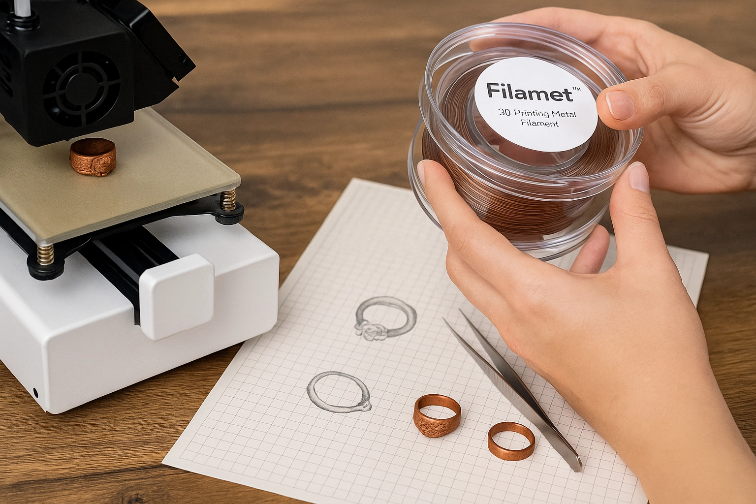
Creative sectors, art and jewelry
Artists leverage metal 3D printing to realize hollow forms, interlocking assemblies, and generative lattices that would be infeasible to cast or fabricate by hand. With Filamet in bronze, copper, or stainless, creators can print thin walls and internal features, then sinter to pure metal and finish via magnetic pin tumbling, abrasive media, and polishing to exhibition quality surfaces. For jewelry, intricate filigree and personalized geometries are practical at feature sizes near 0.5 to 0.8 mm when compensated for predictable sintering shrink. Plan sprues or handling tabs for post processing, maintain uniform wall thickness to minimize distortion, and orient parts to protect show surfaces. Weight can be reduced through lattice infill while preserving stiffness, improving wearability without compromising strength. Consistent dimensional control comes from measured shrink factors per alloy and kiln schedule, applied directly in CAD.
Education and engineering learning
Universities and labs use Filamet to convert existing FFF platforms into metal AM workcells, giving students end to end practice from CAD to characterization. A typical module includes printing ASTM style tensile coupons, sintering with a documented thermal profile, measuring density by Archimedes method, and correlating microstructure to properties. Teams redesign a legacy bracket for a 20 percent mass reduction under a defined load case, then validate through test. The workflow reinforces DfAM principles, thermal process control, fixture design for sintering, and finishing methods. Safety and quality practices are integral, including kiln ventilation, temperature verification, and traceable records. This hands-on approach prepares graduates to deploy metal 3D printing in regulated sectors and on the shop floor, aligning design choices with post processing and the intended application.
The Future of Metal 3D Printing
Emerging trends: hybrid manufacturing and digital ecosystems
Hybrid manufacturing is shifting from pilot to production, combining additive for complex geometries with subtractive for precision. In FFF-based metal 3D printing, a practical cell prints Filamet™ parts, sinters to pure metal, then machines 0.3 to 0.5 mm allowance on critical faces to reach IT8 tolerances. Datum tabs and sacrificial bosses simplify workholding after sintering. AI-enabled preparation supports topology optimization and thermal simulation that predicts shrinkage and distortion. Industry analyses highlight productivity and quality gains from integrated process chains, see Hybrid manufacturing overview. Digital ecosystems add IoT sensors, machine data, and QC analytics for closed-loop control, illustrated in Digital ecosystems and AI in metal AM.
Market growth projections and opportunities
Analysts project rapid expansion, with the global metal 3D printing market reaching 35.33 billion USD by 2030 at a 24.2 percent CAGR, see Metal 3D printing market size to 2030. Other forecasts estimate 6.9 billion USD in 2025 growing to over 60 billion USD by 2035. Growth is fueled by aerospace and nuclear use cases that require weight reduction, complex cooling, and long-life spares. Recent advances include high-strength aluminum alloys for AM that tolerate 572°F, enabling hotter, lighter engine components, and programs evaluating 3D printed rotor linkages for helicopters. Utilities report success printing certified replacement parts to extend plant uptime, and national labs report safer, stronger AM parts for high-consequence sectors. Opportunities cluster around digital inventories, point-of-use spares, and validated low-volume production, particularly in runs of 1 to 20 units per year.
The Virtual Foundry’s role in shaping the landscape
The Virtual Foundry lowers the barrier to entry by enabling pure metal parts on standard FFF printers with Filamet™, aligning with hybrid workflows. Actionable path forward, set up a compact hybrid cell, FFF printer, sintering furnace, and benchtop CNC, then standardize a thermal profile with a 150°F per hour ramp to 900°F, followed by material-specific holds. Calibrate isotropic and anisotropic shrinkage using witness coupons, then encode these values in your slicer and MES to achieve first-article success. Integrate tumbling and polishing for surface targets, and reserve precision faces for light finishing cuts. This approach supports digital traceability, rapid iteration, and cross-material expansion under the company’s Universal Metal Expansion strategy, positioning teams to adopt AI-driven optimization as monitoring data accumulates.
Conclusion: Embarking on Your Metal 3D Printing Journey
Recap and readiness
From design to densification, this guide showed how metal 3D printing with Filamet converts common FFF workflows into a route to pure metal parts. You leveraged additive’s ability to consolidate complex geometries, reduce waste, and tailor microstructure, while noting that finishing determines performance. Industry signals, including safer, stronger components in aerospace and nuclear programs and rotor-linkage trials on military platforms, confirm the trajectory toward production. Materials are evolving quickly, with high-strength aluminum alloys now sustaining about 572°F, expanding use in thermal environments. For Filamet-built components, tumbling and polishing remain critical to reach jewelry-grade or tooling-ready surfaces, and design for sinter shrink and anisotropy closes the loop.
Practical next steps and community
To begin, define functional loads and temperature exposure for your metal 3d printing project, then select the metal grade accordingly, for example stainless for corrosion control or aluminum when weight and thermal conductivity dominate. Print calibration coupons, measure linear shrink, and update your CAD scale factor before committing to end-use geometry. Follow a conservative furnace profile, a typical debind ramp of 150°F per hour to about 900°F, then proceed to sinter and cool under the material’s recommended atmosphere. Validate surface finish by tumbling and incremental polishing, record Ra and density, and iterate. For pilot production, plan batches in the 1 to 20 units per year range while you lock down fixtures, QC, and documentation. Join the community to share results, access practical datasets, and source materials via The Virtual Foundry: Metal 3D Printing Filament & Supplies, then scale with confidence.