Master Metal Sintering: Step-by-Step Guides for Success

by | Feb 25, 2026 | Sintering

Step-by-Step Sintering Instructions for Metal 3D Printing Post-Processing

Sintering is the high-temperature step that fuses metal, glass, or ceramic powders into a dense, load-bearing solid by promoting particle bonding and densification. In FFF workflows that use binder-filled filaments such as Filamet™ sintering follows printing and debinding to transform a printed “green” part into a fully sintered component with usable mechanical properties. This guide explains why sintering matters, how debinding and sintering interact, and how to plan temperature, atmosphere, and handling to control shrinkage, strength, and surface finish. You will get practical, step-by-step procedures for thermal debinding, material-specific sintering profiles, kiln operation and maintenance, post-sinter finishing and QA, plus troubleshooting techniques targeted to desktop and lab-scale setups. The article is organized across core topics: sintering fundamentals and stages; debinding procedures and safety; detailed Filamet™ material profiles and kiln workflows; post-sinter finishing and measurement; troubleshooting and optimization; equipment and safety requirements; and concise user-facing FAQs to capture common questions. Throughout, terms like densification, green part, brown part, inert atmosphere, and shrinkage compensation are defined and tied to actionable steps so you can move from printed object to dense metal part reliably.

What Is the Sintering Process and Why Is It Essential?

Sintering is a thermal process that joins powder particles by diffusion and neck growth, producing densification and improved mechanical properties without complete melting. The mechanism reduces porosity, increases strength, and refines microstructure so printed, binder-containing parts become functional metal or ceramic components. For filament-based additive manufacturing, sintering is essential because it converts the debound “brown” part—still fragile—into a consolidated, load-bearing part with predictable shrinkage and property profiles. Understanding sintering’s purpose clarifies why controlled temperature ramps, holds, and atmosphere control are required to avoid defects and to reach target density and microstructure.

What Are the Key Stages of the Sintering Process?

The sintering pathway for FFF-derived parts comprises three visible stages: the green part (as-printed, binder-loaded), the brown part (debinding complete or nearly complete), and the sintered part (densified, metallurgically bonded). In the green stage, polymer binder enables extrusion and layer fusion but must be removed or reduced to allow particle contact during sintering. During debinding, binder volatilizes or dissolves, leaving a fragile brown part that retains geometry but lacks strength; careful debinding prevents blistering and internal pressure build-up. Sintering then promotes neck formation, pore shrinkage, and grain growth to reach target density and mechanical performance while inducing predictable linear shrinkage that must be compensated in design.

How Does Particle Bonding and Densification Work During Sintering?

Particle bonding begins with surface diffusion and neck formation between contacting particles; as temperature increases, lattice and grain-boundary diffusion carry material to neck regions, growing connections and reducing pore volume. Diffusion-driven densification reduces the system’s free energy, increases contact area, and produces crystallographic continuity that translates to strength and stiffness gains. Grain growth accompanies densification and must be balanced—excessive growth can reduce toughness while insufficient hold time leaves high porosity. These mechanisms explain why hold temperature, time, and heating rate directly influence final density, grain structure, and the amount of linear shrinkage expected for each material.

What Types of Sintering Are Used in Metal 3D Printing?

Several sintering variants apply to printed powders and binder-filled filaments: conventional solid-state sintering, liquid-phase sintering where a eutectic melts to aid densification, vacuum sintering that reduces oxidation, and inert-gas sintering using argon or nitrogen to protect reactive metals. Desktop and educational setups commonly use solid-state approaches in controlled inert atmospheres or vacuum chambers, while liquid-phase methods are used when specific alloy compositions benefit from transient liquid phases during densification. Pressure-assisted methods (hot isostatic pressing) offer superior densification but are not typical for hobbyist bench kilns; selecting a method revolves around material chemistry, oxidation sensitivity, and desired final properties.

Which Parameters Affect Sintering Quality?

Sintering quality depends on temperature, hold time, heating/cooling rates, atmosphere composition, part geometry, particle packing, and initial binder content. Temperature controls diffusion rates and grain growth, hold time allows neck growth and pore elimination, while ramp rates influence thermal gradients that can cause warping or cracking. Atmosphere prevents oxidation and contamination for reactive metals—argon reduces surface oxide formation for copper and bronze, while vacuum sintering minimizes trapped gases. Understanding these parameters enables targeted profile design to balance densification, dimensional accuracy, and microstructure.

How Do You Perform the Debinding Process Before Sintering?

Debinding removes most of the polymer binder from a printed green part so particles can sinter without internal pressure or binder residue causing defects. Effective debinding balances ramp rates and hold steps to let binder outgas or dissolve slowly, avoiding blistering, internal cracking, or steam-driven fractures. Common debinding approaches include thermal (furnace-based slow ramp) and solvent or catalytic methods that extract binder at lower temperatures; choice depends on binder chemistry and equipment availability. Safety and monitoring—mass checks, visual inspections, and staged temperature holds—are essential to verify binder removal before sintering.

What Is Debinding and Why Is It Necessary?

Debinding separates the binder phase from the powder phase: the binder enables printing by providing filament integrity, but if left, it prevents particle contact and produces gas evolution during sintering that can delaminate or explode parts. Removing binder yields a brown part with open porosity and intact geometry that can be handled with care and loaded into the sintering kiln. Incomplete debinding manifests as bubbling, blackened regions, or internal voids after sintering, so verification steps like weight loss checks and scent/visual inspection are used to confirm removal. Proper debinding therefore directly reduces sintering defects and improves final density and surface quality.

How to Debind Filamet™ Parts: Step-by-Step Instructions

Follow a staged thermal debinding procedure tailored for Filamet™ materials: first, dry the printed green part at a low temperature to remove residual moisture, then ramp slowly through low-temperature holds to soften and outgas the bulk binder, and finally perform a higher-temperature dwell to volatilize remaining binder residues. Use mass-monitoring checkpoints—record green part mass, expected mass loss range at each stage, and confirm stability before proceeding to the next temperature step. Small-batch verification is critical: debind sample coupons first, inspect for blistering or surface residue, and adjust ramp rates if off-gassing appears too aggressive. Always allow a controlled cool to room temperature between stages and visually inspect the brown parts before sintering.

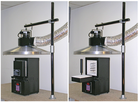
How Should You Set Up and Use a Debinding Kiln Safely?

A debinding kiln must be set up with ventilation to capture binder off-gassing, temperature sensors for accurate control, and remote monitoring or audible alarms to detect abnormal conditions. Personal protective equipment (PPE)—gloves, eye protection, and appropriate respirators when handling fumes—is required during loading and when dealing with solvent-based debinding. Position thermocouples near representative parts to track internal temperatures and implement emergency cooldown procedures in case of runaway decomposition. Maintain clear records of kiln runs, ramp profiles, and observations to build repeatable successful debinding cycles.

What Are Common Debinding Issues and How Can You Troubleshoot Them?

Typical debinding problems include blistering (rapid gas release), cracking (thermal gradients or residual stresses), and residual binder (insufficient temperature or duration). Blistering is often fixed by slowing ramp rates and adding intermediate holds to allow gases to escape gently; cracking can be mitigated by improved support, symmetrical packing, and slower ramps to reduce thermal gradients. If residual binder remains, extend hold times at the low-to-mid debind temperature range and verify with mass checks and surface inspection. Preventive measures include designing vent paths in parts, orienting prints for even wall thickness, and using sacrificial test coupons to refine profiles.

How to Sinter Filamet™ Materials: Detailed Temperature and Time Profiles

A consistent sintering workflow converts a debound brown part into a dense, functional object by following material-specific temperature ramps, atmosphere selection, and hold times tuned to the Filamet™ powder chemistry. The table below provides representative sintering targets for several Filamet™ materials—temperatures, recommended hold times, atmosphere guidance, and expected linear shrinkage ranges—to use as a starting point for small-batch verification. Treat these profiles as examples: always validate with test coupons and adjust for part size, packing density, and kiln characteristics. For users seeking materials and kits that simplify print→debind→sinter workflows, The Virtual Foundry, Inc. offers Filamet™ materials, sintering kilns, and Filamet™ kits designed for compatibility with open-architecture printers and common desktop kilns.

MaterialSinter Temp (°C)Hold Time / AtmosphereExpected Shrinkage (%)
Copper Filamet™1052°C (1925°F)1–3 hr hold in reducing/inert (argon)12–18%
Stainless Steel 316L Filamet™1250–1350°C (2282–2462°F)1–4 hr in vacuum or hydrogen-reduced atmosphere14–20%
Bronze Filamet™885°C (1625°F)1–3 hr in inert (argon) or mild reducing10–16%
Glass Filamet™560–760°C (1040–1400°F) anneal30–120 min hold in air, controlled cool6–12%
Ceramic Filamet™1200–1600°C (2192–2912°F)1–6 hr in air or inert depending on chemistry10–25%
Rapid 3DShield Tungsten2500–3400°C (4532–6152°F) (specialty sintering)Specialty furnaces; inert or vacuumVariable (specialty)

These representative profiles illustrate typical sintering windows and expected linear shrinkage for common Filamet™ formulations; use them to scale prints and design sinter fixtures. After table verification, run small coupon sets to measure actual shrinkage and density; iterative adjustments of hold time and atmosphere often yield the best results.

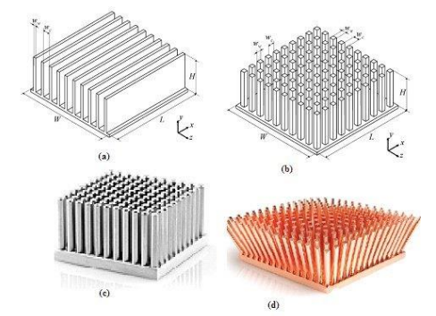
Sintering Simulation for Metal Fused Filament Fabrication

Metal Fused Filament Fabrication (MFFF) offers a huge potential for complex metallic parts. When manufacturing metal components using sinter-based additive manufacturing, the sintering process poses the greatest challenges. Additively manufactured green parts shrink by up to 30% during sintering depending on factors, such as material composition, process variables during printing and sintering as well as the geometry of the green part. To predict shrinkage and support the development of new components a simulation is helpful to reduce defect production, improve dimensional accuracy, systematize the process and detect undesirable deformations. As a plus, the simulation improves the understanding of the process chain. Sintering simulation has been used recently for different manufacturing technologies apart from MFFF printed components. As part of this paper, the commercial and established software Simufact Additive from Hexagon AG is applied to MFFF components made of the material SS316L, using a module which was intentionally developed for Metal Binder Jetting-based process routes. The effects of MFFF proprietary process parameters and two sintering cycles with different parameters (sintering temperature, holding time, and heating rate) on the properties of the metallic components were examined.

Sintering simulation and validation for the sinter-based fused filament fabrication process route, J Telgkamp, 2025

What Is the General Sintering Workflow for Filamet™ Metal, Glass, and Ceramic Filaments?

The general workflow begins with loading brown parts into the sintering kiln with consistent packing density and support to minimize distortion during shrinkage. Ramp at controlled rates to the sintering temperature, include prescribed hold times for densification, and then apply a controlled cooling schedule or anneal as needed to avoid thermal shock. Monitor atmosphere composition and pressure—swap to inert gas or vacuum before reaching oxygen-sensitive ranges—to prevent surface oxidation or contamination. After the sinter cycle, allow parts to cool under protective atmosphere or in a controlled environment before handling to preserve surface quality.

What Are the Recommended Sintering Temperatures and Hold Times for Each Filamet™ Material?

Use the profile table above as a baseline but remember each kiln, batch size, and part geometry alters thermal mass and effective sintering time. For metals, target the lower end of the sintering window for fine-feature parts to limit grain growth, and extend hold times for larger parts to ensure uniform densification. Glass filaments require specific annealing holds and slow cooling ramps to relieve internal stresses and avoid cracking, while ceramics typically need higher peak temperatures and longer holds to eliminate porosity. Always sinter test coupons and measure density, then adjust profiles incrementally rather than making large jumps between runs.

How Does Atmosphere Control Impact Sintering Results?

Atmosphere control prevents oxidation, modifies surface chemistry, and can accelerate or inhibit certain sintering mechanisms depending on the gas used. Argon or nitrogen provide inert environments that protect copper and bronze from oxidizing; vacuum sintering reduces trapped gases and helps reduce contamination for stainless steels and high-temperature alloys. Reducing atmospheres (hydrogen-containing systems) can remove surface oxides but require strict gas-handling safety. For small shops, purging with inert gas and using sealed fixtures or getter materials can reduce oxidation without complex gas systems.

How to Operate and Maintain Your Sintering Kiln for Best Results?

Operate kilns with regular thermocouple calibration, validated ramp programs, and consistent chamber loading to reproduce sintering conditions across batches. Place thermocouples near representative parts, log temperature profiles, and perform periodic calibration checks against reference sensors to ensure accuracy. Maintain the chamber by cleaning residues, replacing worn insulation and heating elements as needed, and inspect seals and atmosphere lines for leaks. A maintenance log and scheduled calibration program improve repeatability and reduce variability between sintering runs.

What Post-Sintering Steps Are Needed to Finish Your Metal 3D Printed Parts?

After sintering, controlled cooling and careful handling protect parts from thermal shock and contamination while post-processing restores surface finish and validates mechanical properties. Typical post-sinter steps include slow cooling under protective atmosphere or in a controlled oven, mechanical finishing such as sandblasting or polishing, optional machining or CNC operations for tolerances, and quality assurance tests like density or hardness checks. Plan for shrinkage compensation and dimensional measurement during finishing, and apply appropriate surface treatments depending on the intended application—jewelry, structural, or decorative. Proper post-sinter choices ensure parts meet functional and aesthetic goals.

How Should You Cool and Handle Sintered Parts Safely?

Cool sintered parts under controlled rates when possible to avoid thermal gradients that can warp or crack brittle sections; slow cooling is especially important for glass and ceramic compositions. Handle parts with gloves and clean tools to avoid introducing oils or contaminants on hot surfaces, and stage parts in a clean, low-humidity area to prevent rapid temperature changes. When moving parts from protective atmospheres to air, ensure surfaces are stable—some alloys develop fragile surface oxides if exposed too soon. Use fixtures or pallets that accommodate shrinkage and provide mechanical protection during handling.

What Surface Finishing Techniques Improve Part Appearance?

Surface finishing options include abrasive blasting for matte uniform textures, mechanical polishing for high gloss, and light machining for critical tolerances; chemical polishing or plating may be appropriate for jewelry or conductive surfaces. Each method balances surface roughness, dimensional change, and cost; sandblasting is fast and removes oxide scale, polishing improves aesthetic and tactile quality but removes material, and plating can mask porosity and change corrosion resistance. Choose finishing based on part function: fine jewelry favors polishing and plating, functional parts favor machining and light blasting to preserve geometry. Test finishes on sacrificial coupons to validate appearance and tolerance impacts.

How Do You Measure and Ensure Desired Material Properties?

Common tests include density measurement using Archimedes’ method, hardness testing with micro- or macro-hardness scales, and tensile or bend testing on standardized coupons to evaluate mechanical performance. Microstructural analysis via optical microscopy reveals grain size and porosity distribution that correlate with material properties, while dimensional inspections compare post-sinter geometry to compensated CAD models. Simple lab methods and inexpensive hardness testers provide practical acceptance criteria for many users; set target ranges for density and hardness and iterate sintering profiles until coupons meet those targets. Recording all measurements enables process control and reproducible results.

Property / TestMethodTarget Value / Acceptance Criteria
DensityArchimedes immersion≥ 95% theoretical density (material dependent)
HardnessRockwell or VickersWithin spec range for chosen alloy
Dimensional accuracyCalipers / CMMWithin compensated tolerance ± allowable mm
PorosityOptical inspectionMinimal interconnected porosity; < specified %

This table summarizes common QA checks to validate a sintered part’s readiness for end use; adopting these tests helps close the loop between profile settings and functional outcomes.

Debinding and Sintering of FDM-Printed Ceramic Structures

Shaping and thermal processing of ceramic structures with fused deposition modeling (FDM) is promising, but still a challenging technique. Achieving an optimal compromise between the thermoplastic feedstock properties in terms of 3D printing and debinding behavior is not trivial. In this paper aluminum oxide (Al2O3), zirconium oxide toughened aluminum oxide (ZTA) and ZrO2 (zirconium oxide) thermoplastic filaments were developed for multi-material printing of 2-2 and 3-3 composites using a Bowden extruder with 2.8 mm filament thickness. For all filaments, a thermoplastic binder based on Ethylene Vinyl Acetate (EVA) and stearic acid (SA) with a ceramic filler content of 45 vol.% were used. Increasing the SA content, it was possible to use the solvent debinding process and therefore the thickness of the printed structures could be increased up to 10 mm. After 2 h in acetone solvent, more than 40 wt% could be removed. With additional thermal partial debinding process at 240 °C for 8 h, up to 82 wt% of the thermoplastic binder could be removed successfully. The monolithic printed discs achieved a relative density of 98.2 and 99.1% for the ZTA and the ZrO2 samples, respectively. Finally, the mechanical properties were investigated by ring-on-ring bending test method based on ASTM standard. For ZrO2 discs a mechanical strength of 429 MPa could be achieved.

Debinding and sintering of dense ceramic structures made with fused deposition modeling, F Clemens, 2020

How to Compensate for Shrinkage and Maintain Dimensional Accuracy?

Compensate for linear shrinkage by scaling the CAD model according to measured shrinkage from test coupons—apply isotropic or anisotropic scaling depending on part geometry and observed distortion. A practical formula: scale_factor = 1 / (1 – linear_shrinkage_fraction); measure actual shrinkage percentage after initial runs and apply that factor to future prints. Design features to accommodate sintering: uniform wall thickness, fillets at stress concentrations, and sacrificial supports to hold geometry during shrinkage. Iterative cycles of printing, debinding, sintering, and measurement produce reliable compensation factors for production runs.

How Can You Troubleshoot and Optimize Your Sintering Process?

Troubleshooting begins by categorizing observed defects—porosity, warpage, cracking, oxidation—and then tracing them to parameter causes like insufficient hold time, thermal gradients, or atmosphere failures. Optimization integrates design adjustments, fixture strategies, and incremental changes to temperature and hold times to meet application-specific goals such as maximal density, fine surface finish, or controlled microstructure. Case-based testing—coupons that replicate critical features—enables targeted parameter sweeps and reduces risk to larger production parts. Structured troubleshooting and optimization accelerate the path from prototypes to reliable parts suitable for end-use applications.

What Are the Most Common Sintering Defects and Their Causes?

Common defects and primary causes:

  1. Porosity: Caused by insufficient hold time or low peak temperature.
  2. Warping: Caused by uneven heating or poor fixturing.
  3. Cracking: Caused by retained binder or rapid thermal ramps.

These quick associations help prioritize corrective actions such as increasing hold time, improving packing, or slowing ramps.

How Can You Fix and Prevent These Sintering Issues?

Fixes include increasing hold time or peak temperature to reduce porosity, redesigning fixtures and load patterns to minimize thermal gradients and warping, and adjusting debinding profiles to remove residual binder that causes cracking. Preventive measures include designing parts with uniform wall thickness, using sacrificial supports for thin features, and establishing validated loading patterns that balance thermal mass in the kiln. Documenting successful parameter sets and using standardized coupons as a verification step before full production minimizes recurrence of defects.

How to Optimize Sintering Parameters for Specific Applications?

Prioritize objectives: jewelry and fine-detail parts often require lower peak temperatures and shorter holds to preserve surface detail, while structural components require longer holds and higher densification to maximize strength. Create archetypal parameter sets for each application class (e.g., fine-detail bronze vs. load-bearing stainless) and test with targeted coupons to confirm mechanical outcomes. Use trade-off analysis: increased hold time improves density but coarsens grain; choose parameters aligned with the dominant performance requirement. Iterative design-of-experiments helps identify the most efficient path to target properties.

What Are Real-World Case Studies Demonstrating Successful Filamet™ Sintering?

Example projects demonstrate how parameter tuning and fixture design solved common issues: an educational lab produced bronze jewelry by iterating anneal and polishing steps to control shrinkage and surface finish; a research group scaled copper prototypes by switching to argon atmosphere and slightly longer holds to reduce oxidation and porosity. These short case studies show the value of coupon-based testing, gradual profile adjustments, and post-sinter finishing to meet aesthetic and mechanical goals. Lessons learned include prioritizing atmosphere control for reactive metals and designing test coupons that replicate critical thin features.

What Equipment and Materials Are Required for Effective Sintering?

Effective sintering requires an integrated toolset: a well-calibrated FFF printer for consistent green parts, a debinding kiln with controlled ramp capability, a sintering kiln capable of target peak temperatures and atmosphere control, gas handling or vacuum systems where required, and QA tools for density and hardness testing. Selection decisions hinge on the sintering temperature range, chamber volume, and atmosphere requirements for your chosen Filamet™ material. Filamet™ kits and compatible sintering kilns from The Virtual Foundry, Inc. provide matched components for common desktop workflows, while additional accessories—thermocouples, fixturing trays, and gas purging components—improve repeatability and safety.

What Are the Essential Tools for Printing, Debinding, and Sintering?

Essential tools include a reliable FDM printer with open-architecture filament access, a debinding furnace with programmable ramps and ventilation, a sintering kiln rated to the material’s peak temperature and atmosphere needs, and measurement equipment such as precision calipers, scales for mass checks, and a small hardness tester for QA. Additional useful gear: sinter jigs and fixturing trays to prevent distortion, threaded thermocouples for internal monitoring, and blasting or polishing equipment for finishing. Investing in correct temperature range and atmosphere capability for the kiln is more important than large chamber volume when starting with Filamet™ workflows.

EquipmentSpecRecommended Feature / Minimum Requirement
Debinding kilnUp to 400–600°C (752–1112°F)Programmable ramps, venting, mass monitoring
Sintering kilnUp to material peakAccurate control to 1–5°C (34–41°F), atmosphere ports or vacuum
ThermocouplesType K / Type SMultiple channels and calibrated sensors
QA toolsScales, calipers, hardness testerResolution suited to material and tolerance needs

Metal Fused Filament Fabrication of Ti-6Al-4V Alloy

The metal AM of complex geometries is widely accepted and promoted in the industry. While several metal AM technologies exist and are matured to a level where expectation in terms of design and properties are possible to realize. But the metal AM suffers from the heavy expense to acquire equipment, isotropic property challenges, and potential hazards to work with loose reactive metal powder. With this motivation, the dissertation aims to develop the fundamental aspects to print metal parts with bound Ti-6Al-4V powder filaments with the approach of metal fused filament fabrication (MF3). Since fused filament fabrication (FFF) is the most accessible form of AM technology and combining with the conventional sintering process yields the advantage of producing net shape parts to the well-established standards.

Materials-processing relationships for metal fused filament fabrication of Ti-6Al-4V alloy., P Singh, 2020

How to Choose the Right Filamet™ Material for Your Project?

Select Filamet™ materials based on application priorities: choose bronze or copper for aesthetic and thermal properties, stainless variants for corrosion resistance and structural parts, ceramics or glass when high-temperature stability or optical properties matter. Consider shrinkage ranges and sintering atmosphere when choosing material, and plan for small-batch testing to derive accurate compensation factors. For first-time users, Filamet™ kits bundle filament with guidance and tools to reduce setup time and improve early success rates in the print→debind→sinter workflow.

What Safety Precautions Should You Follow During Sintering?

Safety includes capturing binder off-gassing during debinding with adequate ventilation and filtration, following gas-handling protocols for inert or reducing atmospheres, using appropriate PPE when loading hot furnaces, and ensuring emergency cutoff and monitoring systems are functional. Keep combustible materials away from kiln areas, and store gas cylinders and regulators in ventilated spaces per supplier recommendations. Maintain written procedures, training, and incident logs to reduce risk in shop and lab environments.

Safety checklist highlights:

  1. Ventilation: Capture off-gassing and fumes during debinding.
  2. PPE: Use gloves, eye protection, and respirators as required.
  3. Gas Handling: Ensure secure regulators, leak checks, and qualified setup.

A short checklist aids rapid safety compliance and reinforces critical protective steps during sintering workflows.

What Frequently Asked Questions Do Users Have About Debinding and Sintering?

This FAQ block answers common user queries succinctly to help with quick decisions and to target snippet-style answers for common searches.

What Is the Difference Between Debinding and Sintering?

Debinding removes the polymer binder that enabled printing, leaving a porous brown part; sintering then thermally fuses powder particles to densify and produce mechanical strength. Both steps are required: debinding prevents gas-driven defects, and sintering creates metallurgical bonds that produce usable properties. Skipping either step results in weak or failed parts and unpredictable shrinkage.

How Long Does the Sintering Process Typically Take?

Sintering duration depends on material, part size, and kiln power: small metal parts may require 1–4 hours at temperature plus ramp and cool time, while larger parts and high-temperature ceramics can require multi-hour holds and extended cycles. Full cycles including debinding and cooling often span 12–48 hours for common Filamet™ workflows when including slow ramps and safe cooldowns. Use coupons to determine effective cycle times for your specific setup.

What Happens If You Skip or Improperly Perform Sintering?

Skipping or poorly performing sintering leaves parts porous, weak, and prone to fracture; it can also trap binder residue that leads to contamination, deformation, or dangerous off-gassing later. Surface contamination and oxidation may occur, and dimensional tolerances will be unreliable. Proper debinding and sintering are mandatory to achieve predictable mechanical and dimensional outcomes.

What Temperature Ranges Are Used for Different Metal Filaments?

Temperature ranges vary by alloy: copper and bronze typically sinter near 900–1060°C (1652–1940°F), stainless steels require higher temperatures often above 1200°C (2192°F), glass and ceramics follow their own sintering/annealing windows. Refer to material-specific profiles and validate with test coupons rather than relying solely on nominal ranges. Atmosphere selection further constrains allowable temperature-atmosphere combinations.

How Do You Maintain and Calibrate Your Sintering Kiln?

Maintain kilns with regular thermocouple calibration, chamber cleaning, inspection of insulation and elements, and routine checks of atmosphere seals and purge systems. Record calibration checks and maintain a schedule—quarterly thermocouple verification is a practical starting point for active labs. Calibration logs and consistent loading practices improve repeatability between runs.

  1. Thermocouple checks: Verify against a reference sensor regularly.
  2. Chamber cleaning: Remove residues after a defined number of cycles.
  3. Atmosphere checks: Leak test seals and purge lines before runs.

These maintenance steps preserve kiln performance and reduce variability in sintering outcomes.