Each metal additive manufacturing process has its own set of guidelines for ideal part size and shape – Design for Additive Manufacturing – and Filamet™ is no different.
While the open-architecture process that Filamet™ allows gives you unlimited options, there are some parameters that, if followed, will make it easier for you to get the perfect parts you’re after.
But first, let’s talk about those unlimited options.
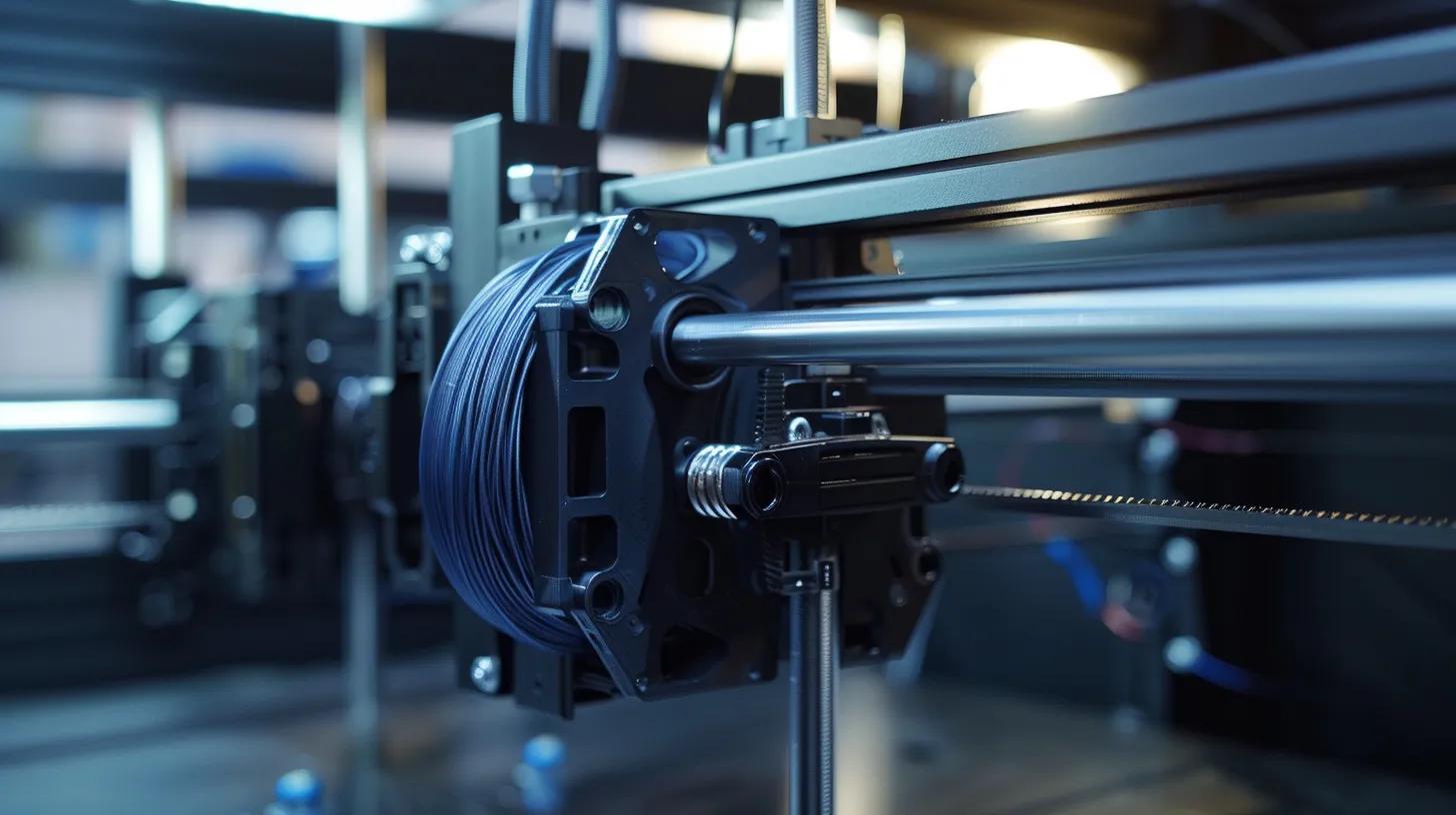
You probably already know that Filamet™ can be printed on most any FFF / FDM printer (use a Filawarmer and a hardened steel nozzle). And that most materials can be debound and sintered in regular kiln / furnace hardware. (Instructions for that are here)
That means you have complete control over every step of your metal part-making process. From layer heights and overlap to ramp rates and temperature holds, these variables are available to you so that you can get the best part possible.
Sometimes people ask about the upper limits of size and truly, the limits are unknown. As you’ll see below, the Filamet™ process is ideal for smaller parts with relatively thin walls (<5mm). Think generative design or topological optimization.
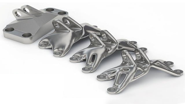
But the real limits are up to you, your equipment and your love for experimentation.
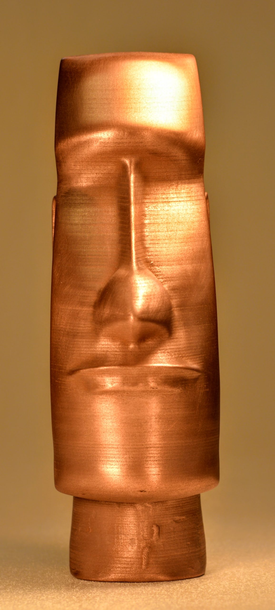
Check out this bad boy. 190mm of pure copper weighing in at 2.7kg
A few part parameters that will contribute to your overall success:
Minimum Infill: 30%
Minimum Wall Thickness: 0.6mm (one nozzle width)
Minimum Hole Size: 1mm diameter
Minimum Unsupported Overhang Angle: 55°
This PDF will give you the rest of the details you need to create the perfect shape.
And remember, 3D Printing offers us a whole host of new opportunities. Try not to print the same part you’ve been making in other ways. Use design for additive manufacturing to change the status quo and bring your parts into the future.
Happy Printing!